In this laboratory students will use Oslo to design, and components from the "Projects in Optics" kit and 2'' lens kit to build a simple Keplerian telescope, a terrestrial telescope with an erecting lens, a Galilean telescope, and a compound microscope.
|
Lens Kit | |
|
Meter Stick, Ruler | |
|
Oslo LT |
![]()
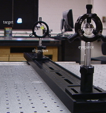
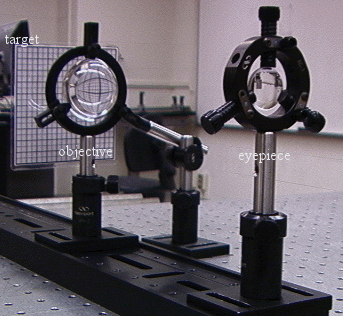
Keplerian Telescope
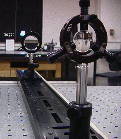
Select lenses from the "Projects in Optics" kit and 2'' lens kit to build a Keplerian telescope with magnifying power MP ~ 5X - 10X. Look up the surface data for these BK7 precision lenses. Use a 2'' lens for the objective and a 1'' lens for the eyepiece.
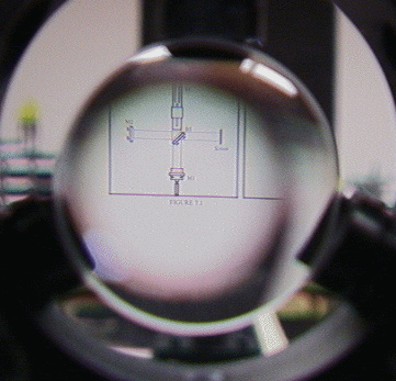
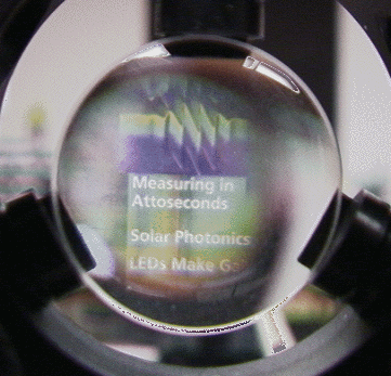
A Keplerian telescope
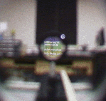
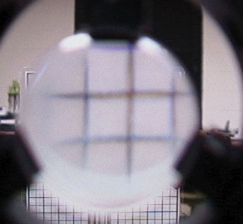
Images of targets with a camera replacing the eye
|
Build your telescope on the optical rail. You can easily slide the components along the rail without destroying the alignment. | |||||||||||||||||
|
Evaluate the performance of your telescope by viewing a distant object. | |||||||||||||||||
|
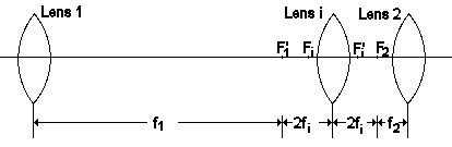
Model your telescope with Oslo. Enter the surface data as described in the write-up for Lab 3.
|
Back of the envelope calculations:
Keplerian telescope, fe << fo, object at infinity:
aperture stop: objective
entrance pupil: objective
exit pupil: (1/(fo + fe) + 1/xi = 1/fe,
xi = fe(fo + fe)/fo
diameter of exit pupil: (fe/fo) * diameter of objective
field stop: eyepiece:
entrance window: (1/(fo + fe) + 1/xi = 1/fo,
xi = fo(fo + fe)/fe
diameter of entrance window: (fo/fe) * diameter of
eyepiece
field of view: tanθ = diameter of eyepiece/(fo
+ fe)
Example: 2'' objective, fo =
300 mm, 1'' eypiece, fe = 50 mm, MP = 6X
exit pupil: xi = 58.33 mm
diameter of exit pupil: 8.5 mm
field of view: tanθ = 0.0726,
θ = 4.15o, full cone angle.
![]()
Terrestrial Telescope
Design and build a terrestrial telescope with magnifying power MP ~ 5X - 10X.
|
Select a bi-convex erecting lens to be mounted between the objective and eyepiece. | |
|
Evaluate the performance of your telescope by viewing a distant object. |
Example: 2'' objective, fo =
300 mm, 1'' eyepiece, fe = 50 mm, 2'' erecting lens, fi
= 50 mm
aperture stop: objective
entrance pupil: objective
exit pupil: xi = 108.33 mm
diameter of exit pupil: 8.5 mm
field stop: eyepiece
field of view: tanθ = 0.039,
θ = 2.24o.
![]()
Galilean Telescope
|
Design and build a Galilean telescope with magnifying power MP ~ 5X - 10X. | |
|
Evaluate the performance of your telescope by viewing a distant object. |
A Galilean telescope An image with a camera replacing the eye
Back of the envelope calculations:
Galilean telescope, fe is negative, |fe| << fo, object at infinity:
aperture stop: objective
entrance pupil: objective
exit pupil: (1/(fo + fe) + 1/xi = 1/fe,
xi = fe(fo + fe)/fo
diameter of exit pupil: (|fe|/fo) * diameter of objective
field stop: eyepiece:
entrance window: (1/(fo + fe) + 1/xi = 1/fo,
xi = fo(fo + fe)/fe
diameter of entrance window: (fo/|fe|) * diameter of
eyepiece
field of view: tanθ = diameter of eyepiece/(fo
+ fe)
Example: 2'' objective, fo =
300 mm, 1'' eyepiece, fe = -50 mm, MP = 6X
exit pupil: xi = -41.66 mm
diameter of exit pupil: 8.5 mm
field of view: tanθ =0.1, θ
=5.8o.
![]()
Compound Microscope
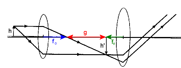
Design a simple compound microscope with a tube length g of 160 mm and a magnifying power MP ~20. 160 mm is the most common tube length for laboratory microscopes. Use the 38 mm focal length 2'' converging lens as the objective and the 50 mm focal length 1'' diameter converging lens as the eyepiece. Let the center to center distance between the lenses be ~25cm. Place the target ~5 cm in front of the objective.
A compound microscope An image with a camera replacing the eye
|
Build the microscope on the optical rail. | |
|
Evaluate the performance of your microscope by examining a tiny object of your choice. |
![]()
Open Microsoft Word and prepare a report using the template shown below.
| In a few words, describe the experiment. (What?) | |
| In a few words, state the objective of the experiment. (Why?) | |
| Comment on the procedure. Did you encounter difficulties or surprises? (How?) | |
| Present your results and comment on your results. |