

Michelson Interferometer
The Michelson interferometer is an optical instrument of high precision and versatility. It is generally used in investigations that involve small changes in optical path length. With the Michelson interferometer, one can produce circular and straight-line fringes of both monochromatic light and white light. One can use these fringes to make an accurate comparison of wavelengths, measure the refractive index of gases and transparent solids, and determine small changes in length quite precisely. The Michelson interferometer was introduced by Albert Michelson in 1881. It has been used to
| provide experimental evidence for special relativity, | |
| discover the hyperfine structure in the energy levels of atoms, | |
| measure tidal effects of the moon on the earth, | |
| enable the use of wavelength of light as the international standard for the meter. |
The Michelson interferometer operates on the principle of division of amplitude rather than on division of wave front. According to this principle, the incident beam of light falls on a beam splitter, which reflects roughly half of the intensity of the wave front in one direction and transmits the other half of the intensity of the wave front in another direction. The two beams, which travel different optical paths, are subsequently recombined in a common region where interference occurs and fringes are formed. The character of the fringes is directly related to the difference in the optical path lengths for the two beams. It is therefore related to whatever causes a difference in the optical path lengths.
In its most common arrangement, a Michelson interferometer is illuminated by an extended source S and consists of a 50% beam-splitter BS and two mirrors M1 and M2. The interference pattern is observed on a screen that is either very far from BS, or a lens is placed one focal length in front of the screen. Rotation or translation of one or both mirrors changes the interference pattern.
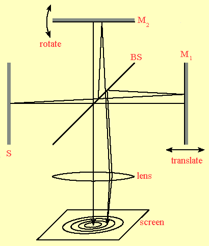
Interference in a Michelson interferometer can be understood in terms of thin-film interference. Imagine that the arms of the interferometer are rotated, such that there is a single optical axis, as shown in the drawing below.
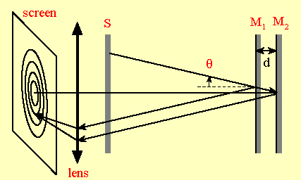
Then reflection from the mirrors M1 and M2 is analogous to reflection from two surfaces of an air gap of thickness d. Since the phase shift upon reflection is the same for both mirrors, we find
2dcosθ = mλ
for constructive interference.
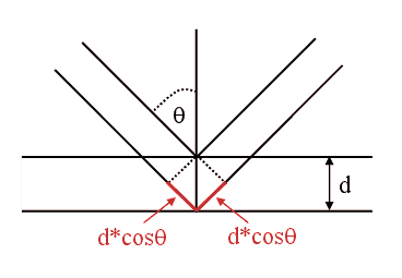
If the two mirrors are precisely aligned such that their planes are exactly perpendicular to one another, thus ensuring that path differences over different regions of the mirrors are constant, the fringe pattern will consist of a series of concentric rings. Each ring will correspond to a different angle of view, measured from the normal to the mirror M1. These fringes are called fringes of equal inclination. They are analogous to fringes of equal inclination that we observe when we shine light from an extended source on a thin film. When the mirror M1 is moved so as to approach the condition for zero path difference, the fringe pattern appears to collapse, with all fringes moving towards the center, and disappear.
![]()
Twyman-Green Interferometer
The Twyman-Green interferometer is a very useful instrument for measuring defects in optical components such as lenses, prisms, plane-parallel windows, laser rods, and plane mirrors. The beam splitter and mirror arrangement of the Twyman-Green interferometer resembles that of a Michelson interferometer. The difference lies in the way the interferometers are illuminated. While the Michelson interferometer is used with an extended light source, the Twyman-Green interferometer is used with a monochromatic point source which is located at the principal focus of a well-corrected lens.
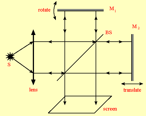
If the mirrors M1 and M2 are perpendicular to each other and the beam-splitter BS makes an angle of 45° with the normal of each mirrors, then the interference is exactly analogous to thin-film interference at normal incidence.
We obtain completely constructive interference when d = mλ/2, where d is the path length difference between the 2 arms adjusted by translating M1. We get complete destructive interference when d = (m + 1/2)λ/2. If we rotate M2, then we see fringes of equal thickness on the screen, since the angle of incidence is constant. This situation is analogous to interference observed with collimated light and a thin film with varying thickness.
When testing optical components, one of the mirrors is intentionally tilted to create fringes. The quality of the component can then be determined from the change in the fringe pattern when the component is placed in the interferometer. Lens testing is particularly important for quantifying aberrations and measuring focal length.
![]()
Fabry-Perot Etalon
This Fabry-Perot interferometer or etalon is a folded Michelson interferometer. With a Fabry-Perot etalon we observe the interference pattern formed by light that is transmitted through two partially reflecting mirrors, while with a Michelson interferometer we observe the interference pattern formed by reflected light.
In its simplest configuration, the Fabry-Perot etalon consists of two plane, parallel, highly reflecting surfaces separated by some distance d. The reflecting surfaces are formed by a very thin silver or aluminum film, or multi-layer dielectric films on the surface of glass plates. The enclosed air gap generally varies from several millimeters to several centimeters. If the gap can be mechanically varied by moving one of the mirrors, the device is referred to as an interferometer. If the mirrors are held fixed and adjusted for parallelism by screwing down on some kind of spacer, it is said to be an etalon.
A Fabry-Perot etalon operates by multiple beam interference. Light which is incident from the left on the first reflection surface is split by reflection into a series of parallel transmitted rays. A ray is partially transmitted at each reflection from the second surface. For simplicity, the figure below does not show the change in direction of propagation of light upon refraction, nor does it show the rays that pass back through the first surface and propagate toward the left.
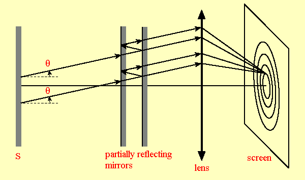
The phase difference between successive reflections is δ = 2π(2ndcosθ/λ). Constructive interference occurs when δ = N2π, or when Nλ = 2ndcosθ, where
| λ is the wavelength of the radiation in vacuum, | |
| d is the separation of the reflecting surfaces, | |
| n is the index of refraction of the material between the reflecting surfaces, | |
| θ is the angle of incidence, | |
| N is an integer. |
The product nd is referred to as the optical thickness to distinguish it from mechanical thickness. Because the wavelength of the light is usually much smaller than the physical separation between the reflecting surfaces, the integer N is on the order of 104 to 105, depending on the mirror separation. The integer N is the order of the interference.
The free spectral range of the interferometer is defined as the change in wavelength necessary to shift the fringe pattern by one fringe.
Nλ =(N - 1)(λ +
ΔλFSR), ΔλFSR
= λ/(N - 1) ~ λ/N,
since N is very large.
Therefore ΔλFSR = λ2/(2ndcosθ)
~ λ2/(2nd),
since cosθ ~ 1.
If the reflectivity R of the mirrors is low, the maxima in the interference pattern will be broad. If the reflectivity is R high, the maxima will be very narrow and sharp. This leads to the concept of the finesse F of the interferometer. The finesse is a measure of the interferometer’s ability to resolve closely spaced spectral lines. The finesse F is defined by the ratio of ΔλFSR to δλ, the FWHM (full width at half maximum) of the constructive interference maximum for a single wavelength. The finesse increases with R.
F = ΔλFSR/δλ = πR1/2/(1-R).
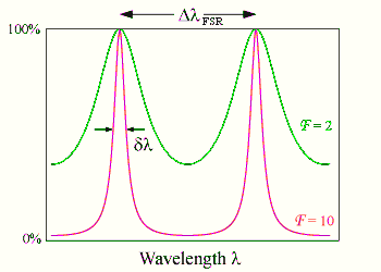
The resolving power RP = λ/δλ is given by the equation
RP = Nλ/(Nδλ) = NΔλFSR/δλ = NF.
Link: The Fabry-Perot Resonator
![]()
Scanning Fabry-Perot Interferometer
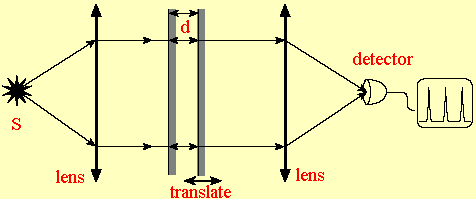
This interferometer is simply a folded Twyman-Green interferometer. It is the collimated light version of the Fabry-Perot etalon. Usually the interferometers is used to measure the spectrum of a source by scanning the separation d between the two partially reflecting mirrors.
![]()
Mach-Zehnder Interferometer
This interferometer is a variation of the Michelson/Twyman-Green interferometer. It produces an interference pattern with the light only making a single-pass through a test component. The Mach-Zehnder interferometer is an important diagnostic tool. It is most frequently used in the fields of plasma physics, aerodynamics, and heat transfer to measure density, pressure, and temperature changes in gases. Because of its relatively large and freely accessible working space and flexibility of location of the fringes, it is the most suitable interferometer to study the airflow around models of aerodynamic structures
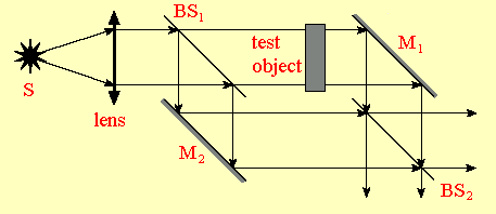
An expanded laser beam is divided by a 50% reflecting, 50% transmitting beam splitter into two beams of equal intensity. After reflection at the 100% reflecting plane mirrors M1 and M2, the two beams are recombined by a 50% reflecting, 50% transmitting beam splitter.
Assume that the recombined beams are intercepted by a well-corrected positive lens, which brings both beams to a focus.
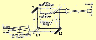
Two beams of light of equal amplitude and wavelength originating from the same source are brought to a focus at S' and S'', respectively, if the reflecting surfaces are nearly, but not perfectly, parallel to each other. The light from the images S' and S'' proceeds on, and the beams interfere in much the same way as in Young’s double slit experiment. In a plane at a right angle to the direction of propagation of the combined beams, an interference fringe pattern will be observed.
If the length of the optical path of one of the beams is changed by inserting a test object into the path of the beam, a new phase shift is introduced between S' and S'' which causes a shift of the fringes. The extent of the shift is a sensitive measure of the change of the optical path length over the two dimensional fields of view.