

Consider an optical system composed of lenses with spherical surfaces centered on an optical axis, with all principal planes perpendicular to this optical axis. In particular, consider a single lens centered on an optical axis, with its principal planes perpendicular to this optical axis. In the paraxial approximation, such a system is a perfect optical system. Every ray that leaves a given object point P successfully travels to the corresponding image point P’.
But the paraxial approximation is a first-order approximation. We start with the exact equations for the propagation of a ray that crosses a spherical boundary between two media. We then expand all terms containing sinθ and cosθ in powers of θ and keep only terms containing θ to the 0th and 1st power. Here θ is any angle the ray makes with the normal to the interface.
We now ask what happens if we are dealing with rays that make large angles θ with the normal to the interface. Such rays leaving a given object point P will no longer meet at the image point P’, and the image will no longer be a sharp point. This defect in the image is called a lens aberration or a geometrical aberration.
| Spherical aberration,
coma, and astigmatism are
point aberrations.
The image of a point light source is not a single point. Spherical aberration is the only aberration that can be associated with a point
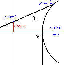
on the optical axis. All light rays leaving a point on the optic axis are meridional rays. For a meridional
ray the object point, the point where the ray strikes the interface, and the
optical axis all lie in one plane, as shown in the figure on the right. Coma and astigmatism require an off-axis object point. In the paraxial approximation all rays behave like meridional rays, since the equations for the projections of the rays on the xz-plane and on the yz-plane decouple and the projections can be treated independently. But θ does not have to be small for all meridional rays. All meridional rays do not have to obey the paraxial approximation. |
 |
![]()
Spherical Aberration
Spherical aberrations are the consequence of the failure of meridional rays to obey the paraxial approximation.
Let us investigate spherical aberrations for a single lens using the exact ray tracing equations for meridional rays.
Let us consider a double convex lens with radii of 50 mm and thickness of 15 mm and with index of refraction n’ = 1.5 surrounded by air (n = 1). The paraxial image focal point lies 47.37 mm from the exit vertex of the lens.
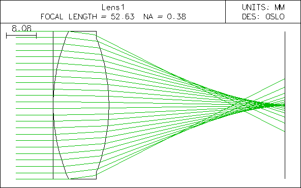
| The figure above shows rays incident parallel to the optical axis from a very
distant on-axis object point. They
are refracted as they travel towards the paraxial focal plane. Rays that
are close to the axis meet at or close to the paraxial focal point F’, while
those incident near the edge fall short by a large amount. Rotating this
diagram about the optical axis reveals a very blurry circular image in the
paraxial plane. The least blurry image is produced a short distance to the
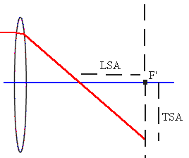
left of the paraxial focal plane and is called the circle of least confusion. The figure on the right shows how to define spherical aberrations quantitatively for the parallel ray farthest away from the optical axis in a given system. The distance between the paraxial focal plane and the place where the ray crosses the optical axis is called the longitudinal spherical aberration (LSA). The distance of the ray from the optical axis at the paraxial focal plane is called the transverse spherical aberration (TSA). |
 |

Link: YouTube, Spherical Aberration
The amount of refraction at the two surfaces of the lens is not the same. Spherical aberrations can be reduced by equalizing the amount of refraction at both surfaces of a lens. This can be done by varying the shape of the lens, while keeping the index of refraction, thickness, and focal length constant. Only the radii of the lens are changed. This is called bending the lens.
The optimization feature of the ray tracing program OSLO lets us vary the radii of the lens to minimize the spherical aberration. The results are shown below.
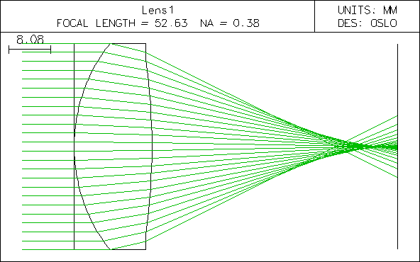
The radii of the two lens surfaces are now chosen to be 32.36 mm and -119.08 mm respectively.
Spherical aberrations dominate when a wide beam, which is parallel to the optic axis, is focused by a converging lens with spherical surfaces. The focal length for rays which travel through the outer regions of the lens is shorter than that for the rays traveling through the center of the lens.
![]()
Coma
| Additional point aberrations are associated with point sources that do not
lie on the optical axis. We now must deal with rays that do not lie in the meridional plane.
These are non-meridional or skew rays. Coma is the failure of skew rays to match the behavior of meridional rays. In the figure on the right a cylinder of rays fom a distant point source is centered about the optical axis of a lens. All rays are meridional, but they are not paraxial. However, they meet at a common image point, forming a cone whose apex is that image point. Now assume that the cylinder of rays is displaced downward while the intersection points of the rays with the dotted, red circle are held fixed. (Equivalently, imagine that the lens is tilted towards the right.) After this tilting, all rays except the top and bottom ray are no longer meridional, but skew rays. |
|
| The top and bottom meridional ray meet at a point P in image space. Let
this point define an image plane. The ray just below the uppermost ray on
the right side of the lens, as seen from the beam direction, passes through this
plane slightly to the right and a little below P. As we step through the
rays from the top to the bottom ray on the right side of the lens, we find that
the points where the rays pass through the image plane trace out a closed,
approximately circular, curve. We get the same pattern for the rays on the
backside of the lens. If coma were the only aberration (ideal coma), then
the two closed curves would coincide. If spherical aberration is also
present, the two closed curves are shifted sideways with respect to each other. If we now do not just have one cylinder of rays, but a beam made up of cylinders with a continuous distribution of radii, then we can picture a generation of image curves. The lines tangential to the coma circles make an angle of 60o with each other. Link: YouTube, coma aberration |
|
Coma aberrations degrade the image of an off-axis object point. The point is imaged to a blob, whose shape resembles that of a comet tail. A streak of light appears to emanate from a focused spot. On a sunny day use a magnifying glass to focus an image of the sun. When you tilt he magnifying glass with respect to the line of sight to the sun, the sun's image will elongate into a comet-like shape that is characteristic of coma aberration.
![]()
Astigmatism
Spherical aberration is the failure of meridional rays to obey the paraxial approximation, and coma is the failure of skew rays to behave like meridional rays. What happens if we design the lens to minimize these aberrations?
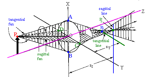
In the figure above, consider the object point P. Let P be the source of a meridional fan. The top ray of this fan is labeled PA and the bottom ray is labeled PB. If the lens is completely corrected for spherical aberration, this fan will have a sharp image point P’T lying directly below the optical axis. Now let P also be the source of a fan bounded by the rays PC and PD. This fan is at right angles to the other one and all rays except the central ray of this fan are skew rays. If the lens has no coma, this fan also will produce a sharp image point P’S, which, for a converging lens, will be farther from the lens than the tangential focal point. In other words, even though the lens has been fully corrected for spherical aberration and coma, the two corrections will not necessarily produce a common image. In the figure, the meridional fan is called a tangential fan and the skew fan is called a sagittal fan.
| Look at the sagittal image point P’S. This point is a distance zS from the x-y plane. A plane through this point will contain an image, the sagittal line, due to the tangential fan, which has already come to a focus and is now diverging. Now look at the tangential image point P’T. This point is a distance zT from the x-y plane. A plane through this point will contain an image, the tangential line, due to the sagittal fan, which is still converging. If we locate an image plane halfway between the two, then both fans contribute to the image, and, in the ideal case, the image will be a circle. As the image plane is moved forward or backward, the images become ellipses and eventually reduce to a sagittal or a tangential line. | 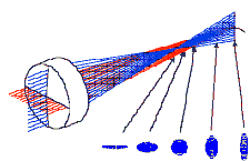 |
The failure of the sagittal and tangential rays to produce a single image in a lens corrected for both spherical aberration and coma is known as astigmatism.
Astigmatism aberrations degrade the images of off-axis object points formed by lenses with spherical surfaces and the images of all points formed by lenses with two different radii of curvature in two perpendicular planes. (Lenses that are shaped more like a football than a sphere.) The image of an off-axis point appears as a line or ellipse instead of a discrete point. Rays that propagate in two perpendicular planes have different focal points. Astigmatism is very common in the human eye.Because there are two different image planes, an object with spokes can have an image for which the vertical lines are sharp, but lines that make an angle with the vertical become more and more blurred as that angle approaches 90o. If the other image plane is chosen, horizontal lines can be sharp and vertical lines are blurred. Eye examinations detect astigmatism if the spokes appear to go from black to gray.
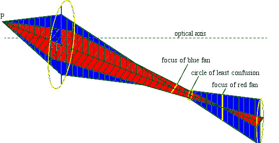
If we move a screen into the focal plane of the blue fan, then the image of a point is a horizontal line segment. The image of a series of points forming a horizontal line will be a sharp horizontal line formed by overlapping horizontal line segments. But the image of a series of points forming a vertical line will be a very blurry vertical line formed by vertically stacked horizontal line segments. If we move the screen into the focal plane of the red fan, then the image of a point is a horizontal line segment. Now the image of a series of points forming a vertical line will be a sharp vertical line formed by overlapping vertical line segments. But the image of a series of points forming a horizontal line will be a very blurry horizontal line formed by horizontally stacked vertical line segments.
Link: Astigmatism (Java applet)
![]()
| Curvature of field Curvature of field is not a point aberration, but an aberration associated with an extended object.
When extended objects are imaged with spherical lenses all
transverse points on the image are |
|
|
|
|
Distortion Another aberration associated with extended objects is distortion. Distortion results when the magnification is a function of the distance away from the optical axis. If we take the object in figure above and move it along the y-axis, then all rays leaving it are skew rays. This introduces distortion, the aberration associated with the coordinates normal to the symmetry axis. Distortion is what causes vertical lines to bulge outward (barrel distortion) or inward (pincushion distortion) at the image plane. |
|
Geometrical aberration summary:
Spherical Aberration: Spherical aberrations are point aberrations. Spherical aberrations are the consequence of the failure of meridional rays to obey the paraxial approximation. The image of a point light source on the optical axis is not a point is a blurry circle.
Coma: Coma is a point aberration. Coma is the failure of skew rays to match the behavior of meridional rays. The image of a point light source not on the optical axis is not a point but a blurry, wedge-shaped image.
Astigmatism: Astigmatism is a point aberration. The failure of the sagittal and tangential rays to produce a single image in a lens corrected for both spherical aberration and coma is known as astigmatism. The image of a point light source not on the optical axis is not a point. Its shape (horizontal line, blurry spot, vertical line) depends on the location of the image plane.
Curvature of Field:
When extended objects are imaged with spherical lenses corrected for all point
aberrations, all
transverse points on the image are
Distortion: For extended objects distortion results when the magnification is a function of the distance away from the optical axis.
![]()
Chromatic Aberration
Chromatic aberration results from material dispersion. Because different colors of light refract by different amounts, an image point formed by light of one color does not coincide with the corresponding image point formed by light of a different color. This is not a geometrical aberration.